
Installation and maintenance
Using the product correctly can get a better product experience.


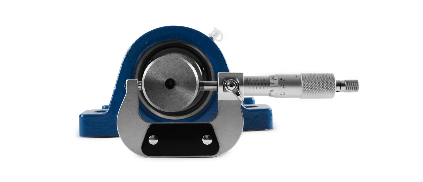
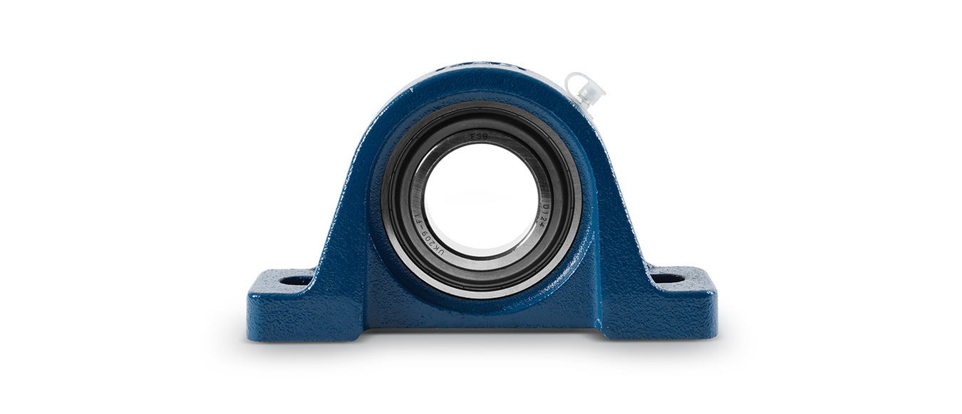
Check whether the rigidity of the base, the flatness of the mounting surface and the dimensional tolerance of the shaft are qualified.
Recommended tolerance table of installation shaft
| Shaft diameter |
UC,SB系列 |
||||||
| Recommended tolerance of shaft (H7) |
|||||||
| mm |
in |
μm |
in |
||||
| > |
≤ |
> |
≤ |
max |
min |
max |
min |
| 10 |
18 |
7/16 |
11/16 |
0 |
-18 |
0 |
-0.0007 |
| 18 |
30 |
3/4 |
1-1/8 |
0 |
-21 |
0 |
-0.0008 |
| 30 |
50 |
1-3/16 |
1-15/16 |
0 |
-25 | 0 |
-0.0010 |
| 50 |
80 |
2 |
3-1/8 |
0 |
-30 | 0 |
-0.0012 |
| 80 |
120 |
3-3/16 |
4-11/16 |
0 |
-35 | 0 |
-0.0014 |
| 120 |
180 |
4-3/4 |
7-1/16 |
0 |
-40 | 0 |
-0.0016 |
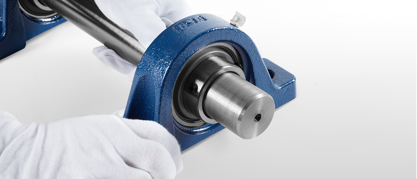
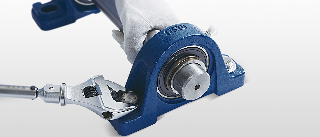
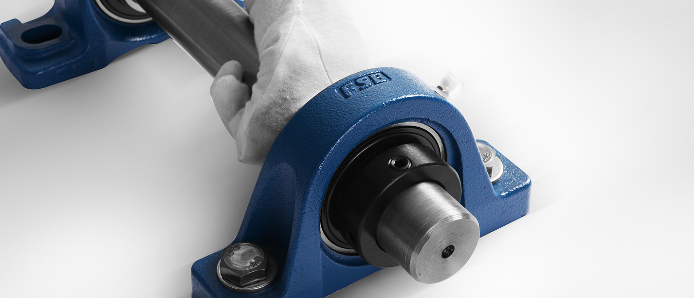
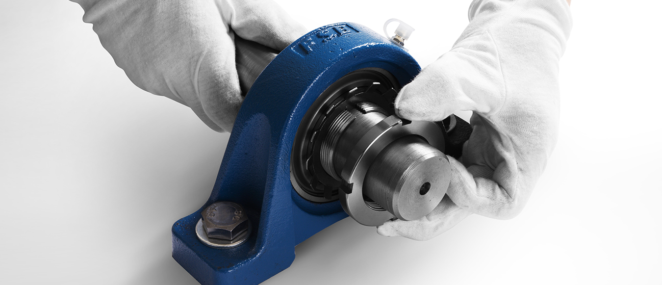
Insert the bearing with seat into the shaft and place it in the specified position.
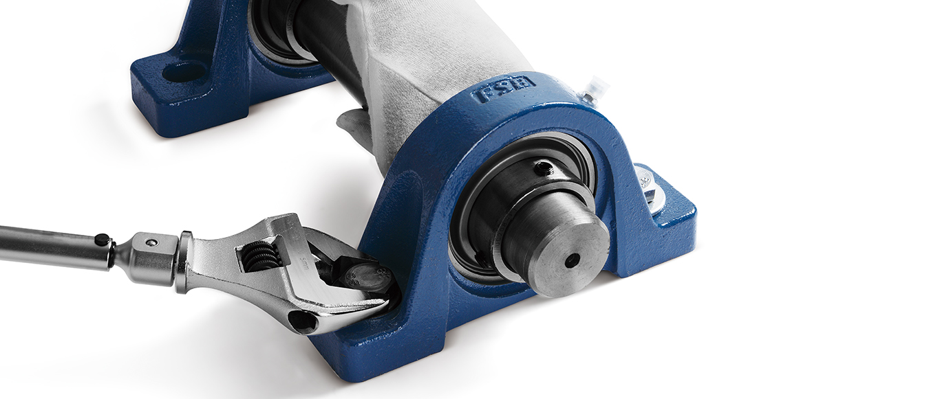
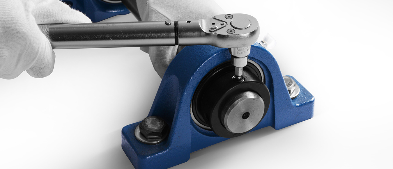
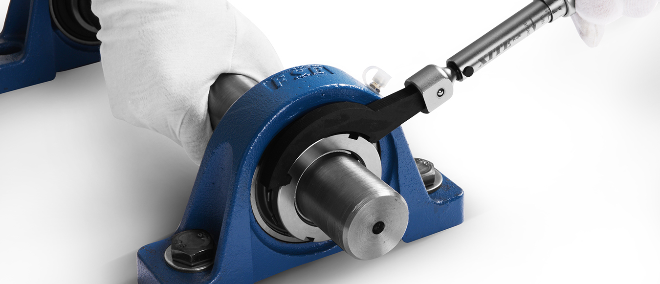
Use a torque wrench to tighten the mounting bolts of the bearing housing according to the specified locking torque.
Recommended table for locking torque of bearing pedestal mounting bolt
| Nominal model of bolt |
Locking torque(±10%) |
|||
| mm |
in |
N.m |
lbf.in |
lbf.ft |
| M6 |
1/4 |
4.0 |
33 |
3 |
| M8 |
5/16 |
8.0 |
71 |
6 |
| M10 |
3/8 |
17 |
151 |
13 |
| M12 |
7/16 |
29 |
257 |
21 |
| M14 |
1/2 |
47 |
416 |
35 |
| M16 |
5/8 |
73 |
646 |
54 |
| M18 |
- |
107 |
947 |
79 |
| M20 |
3/4 |
145 |
1280 |
107 |
| M22 |
7/8 |
200 |
1770 |
148 |
| M27 |
1 |
372 |
3290 |
275 |
| M30 |
1-1/8 |
500 |
4430 |
369 |
| M33 |
1-1/4 |
690 |
6110 |
509 |
| M36 |
1-3/8 |
880 |
7790 |
649 |
Remarks: suitable for P, F, FS, FL, FC, FT, FA, FB, LF, FD bearing pedestal
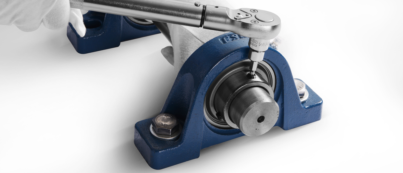
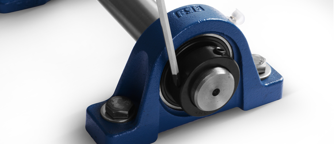
Tighten the stop screw of bearing inner ring equally according to the specified locking torque.
Recommended locking torque table of stop screw
| Nominal model of jacking wire |
Locking torque |
Applicable model |
||||||
| mm |
in | N.m |
lbf.in |
lbf.ft |
UC200 |
UCX00 |
SB200 |
UC300 |
| M5×0.8 |
10-32UNF |
3.0 | 27 | 2.2 | 201-203 (SΦ40) |
201-203 |
||
| M6×1.0 |
1/4-28UNF |
4.0 | 35 | 3 | 201-206 | X05 | 204-206 | 305-306 |
| M8×1.0 |
5/16-24UNF | 9 | 75 | 6 | 207-209 | X06-X08 | 207-211 | 307 |
| M10×1.25 |
3/8-24UNF |
18 | 155 | 13 | 210-213 | X09-X12 | 212 | 308-309 |
| M12×1.5 |
7/16-20UNF |
28 | 248 | 21 | 214-218 | X13-X17 | 310-314 | |
| M14×1.5 |
1/2-20UNF |
35 | 310 | 26 | X18 | 315-316 | ||
| M16×1.5 |
5/8-18UNF |
56 | 496 | 41 | 220 | X20 | 317-319 | |
| M18×1.5 |
5/8-18UNF |
62 | 549 | 46 | 320-324 | |||
| M20×1.5 |
3/4-16UNF |
83 | 735 | 61 | 326-328 | |||
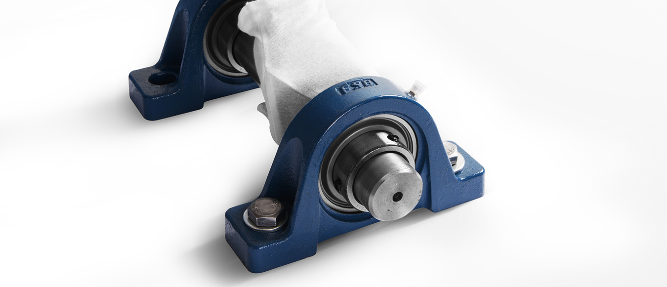
Rotate the shaft by hand to confirm whether the rotation state of the bearing is abnormal.
Check whether the rigidity of the base, the flatness of the mounting surface and the dimensional tolerance of the shaft are qualified.
Recommended tolerance table of installation shaft
| Shaft diameter |
HC,SAseries |
||||||
| Recommended tolerances for shafts(h6) |
|||||||
| mm |
in |
μm |
in |
||||
| > |
≤ |
> |
≤ |
max |
min |
max |
min |
| 10 |
18 |
7/16 |
11/16 |
0 |
-11 |
0 |
-0.0004 |
| 18 |
30 |
3/4 |
1-1/8 |
0 |
-13 |
0 |
-0.0005 |
| 30 |
50 |
1-3/16 |
1-15/16 |
0 |
-16 | 0 |
-0.0006 |
| 50 |
80 |
2 |
3-1/8 |
0 |
-19 | 0 |
-0.0007 |
| 80 |
120 |
3-3/16 |
4-11/16 |
0 |
-22 | 0 |
-0.0009 |
| 120 |
180 |
4-3/4 |
7-1/16 |
0 |
-25 | 0 |
-0.0010 |
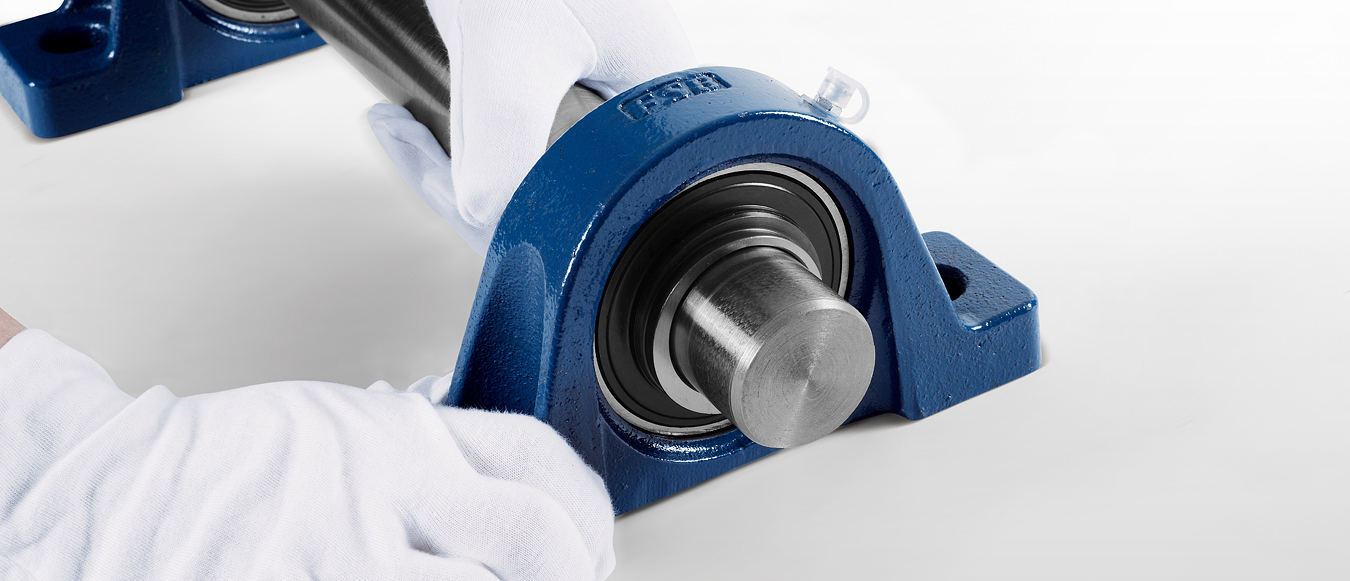
Insert the bearing with seat into the shaft and place it in the specified position.
Insert the bearing with seat into the shaft and place it in the specified position.
Use a torque wrench to tighten the mounting bolts of the bearing housing according to the specified locking torque.
Insert the bearing with seat into the shaft and place it in the specified position.
Recommended table for locking torque of bearing pedestal mounting bolt
| Nominal model of bolt |
Locking torque(±10%) |
|||
| mm |
in |
N.m |
lbf.in |
lbf.ft |
| M6 |
1/4 |
4.0 |
33 |
3 |
| M8 |
5/16 |
8.0 |
71 |
6 |
| M10 |
3/8 |
17 |
151 |
13 |
| M12 |
7/16 |
29 |
257 |
21 |
| M14 |
1/2 |
47 |
416 |
35 |
| M16 |
5/8 |
73 |
646 |
54 |
| M18 |
- |
107 |
947 |
79 |
| M20 |
3/4 |
145 |
1280 |
107 |
| M22 |
7/8 |
200 |
1770 |
148 |
| M27 |
1 |
372 |
3290 |
275 |
| M30 |
1-1/8 |
500 |
4430 |
369 |
| M33 |
1-1/4 |
690 |
6110 |
509 |
| M36 |
1-3/8 |
880 |
7790 |
649 |
Remarks: suitable for P, F, FS, FL, FC, FT, FA, FB, LF, FD bearing pedestal
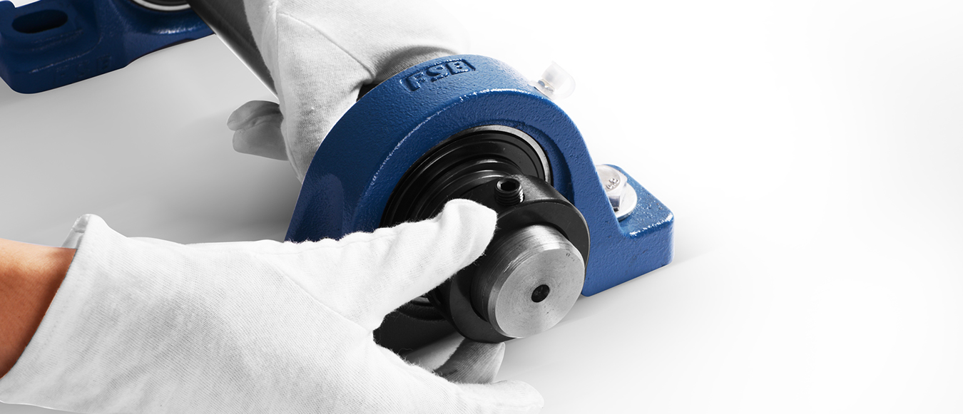
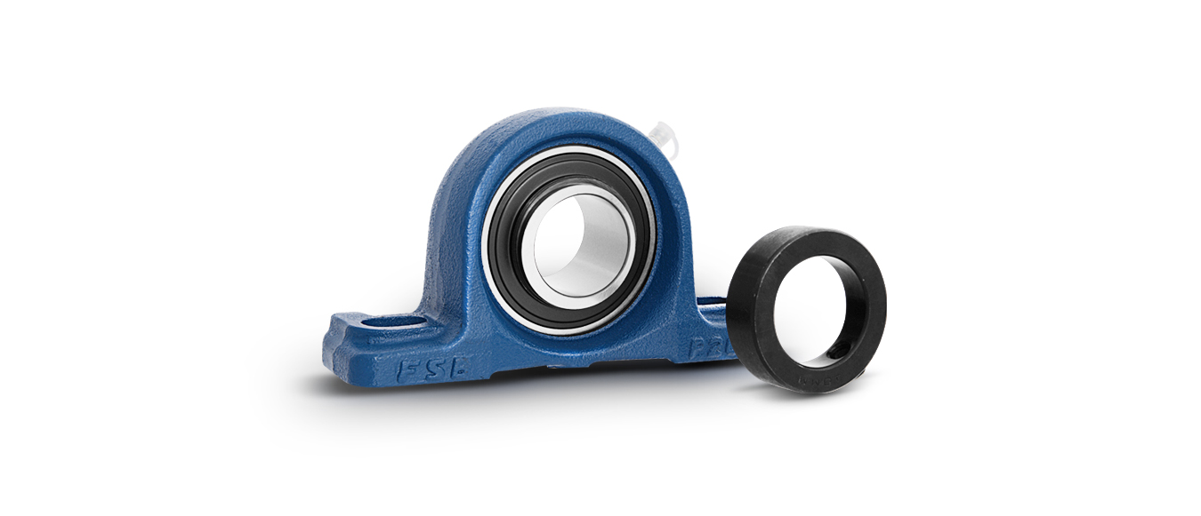
Insert the eccentric part of the eccentric sleeve into the eccentric platform of the bearing inner ring.
Rotate the eccentric sleeve along the rotation direction of the shaft to make it mesh with the eccentric platform of the bearing inner ring, and then knock the eccentric sleeve with a hammer and nail gun along the rotation direction of the shaft to lock it.
Tighten the stop screw on the eccentric sleeve according to the specified locking torque.
Recommended locking torque table of stop screw
|
Nominal model of jacking wire |
Locking torque
|
Applicable model |
|||||
|
mm
|
in
|
N.m
|
lbf.in
|
lbf.ft
|
HC200
|
SA200
|
HC300
|
|
M5×0.8
|
10-32UNF
|
3.0
|
27
|
2.2
|
|
|
|
|
M6×1.0
|
1/4-28UNF
|
4.0
|
35
|
3
|
203-205
|
201-205
|
|
|
M8×1.0
|
5/16-24UNF
|
9
|
75
|
6
|
206
|
206
|
305-307
|
|
M10×1.25
|
3/8-24UNF
|
18
|
155
|
13
|
207-216
|
207-216
|
308-312
|
|
M12×1.5
|
7/16-20UNF
|
28
|
248
|
21
|
211-216
|
211-212
|
313-314
|
|
M14×1.5
|
1/2-20UNF
|
35
|
310
|
26
|
|
|
|
|
M16×1.5
|
5/8-18UNF
|
56
|
496
|
41
|
|
|
315-317
|
|
M18×1.5
|
5/8-18UNF
|
62
|
549
|
46
|
|
|
|
|
M20×1.5
|
3/4-16UNF
|
83
|
735
|
61
|
|
|
318-320
|
Rotate the shaft by hand to confirm whether the rotation state of the bearing is abnormal.
Check whether the rigidity of the base, the flatness of the mounting surface and the dimensional tolerance of the shaft are qualified.
Recommended tolerance table of installation shaft
| Shaft diameter |
UKseries |
||||||
| Recommended tolerances for shafts(h9) |
|||||||
| mm |
in |
μm |
in |
||||
| > |
≤ |
> |
≤ |
max |
min |
max |
min |
| 10 |
18 |
7/16 |
11/16 |
0 |
-43 |
0 |
-0.0017 |
| 18 |
30 |
3/4 |
1-1/8 |
0 |
-52 |
0 |
-0.0021 |
| 30 |
50 |
1-3/16 |
1-15/16 |
0 |
-62 | 0 |
-0.0024 |
| 50 |
80 |
2 |
3-1/8 |
0 |
-74 | 0 |
-0.0029 |
| 80 |
120 |
3-3/16 |
4-11/16 |
0 |
-87 | 0 |
-0.0034 |
| 120 |
180 |
4-3/4 |
7-1/16 |
0 |
-100 | 0 |
-0.0039 |
Recommended tolerances for shafts
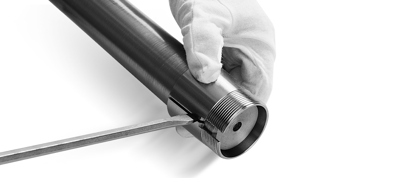
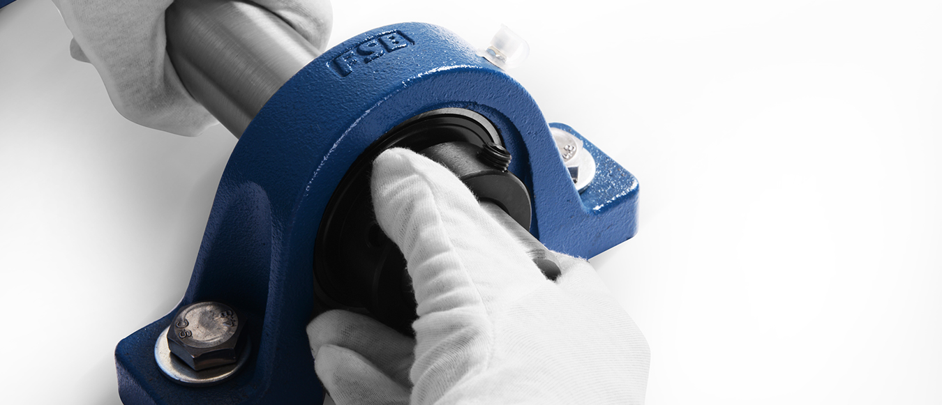
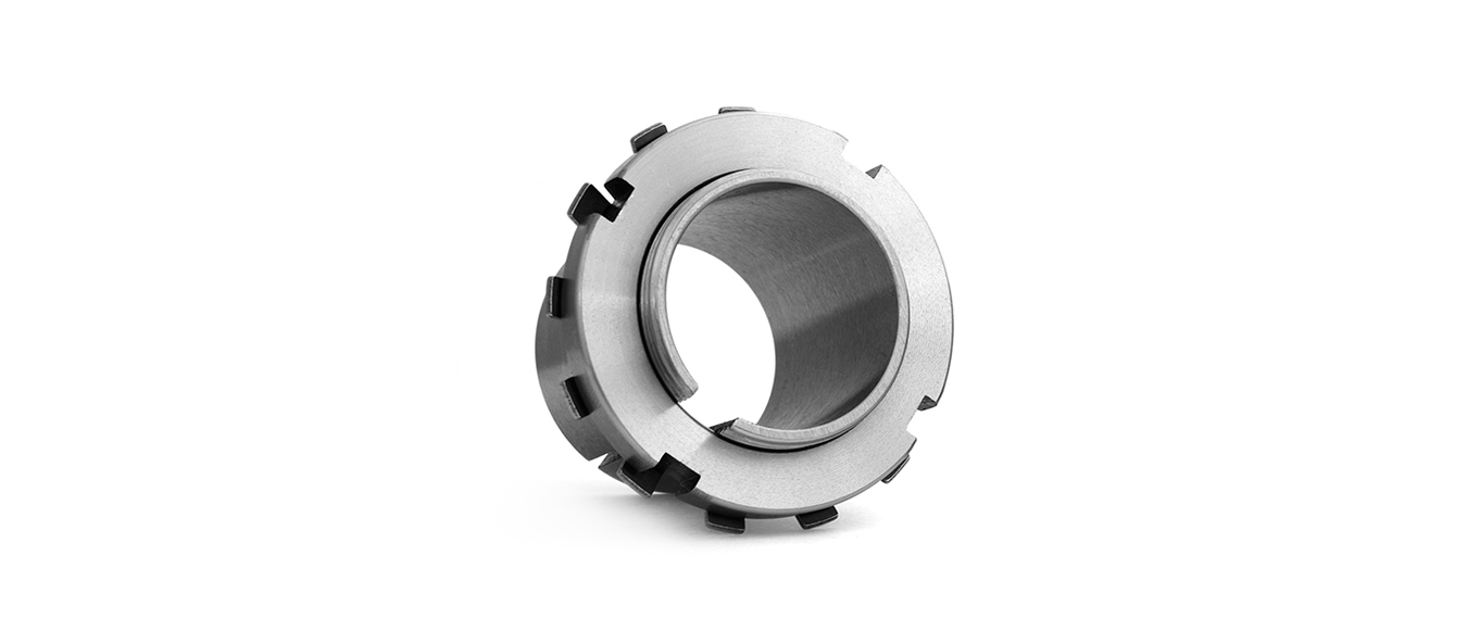
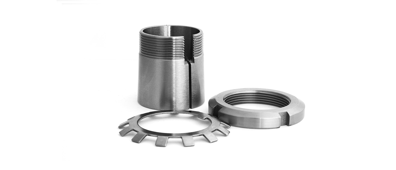
Insert the setting sleeve into the shaft and place it in the fixed installation position of the bearing with seat.
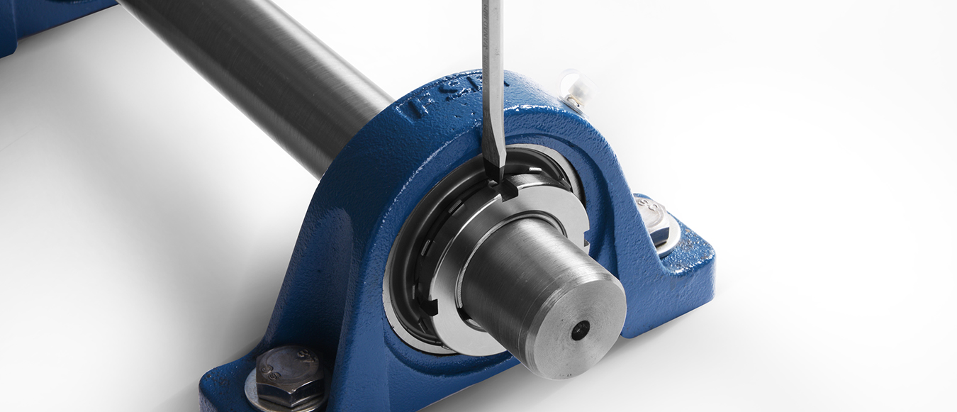
When the setting sleeve is difficult to insert, insert a screwdriver into the slot of the setting sleeve to enlarge the notch to make it easy to insert.
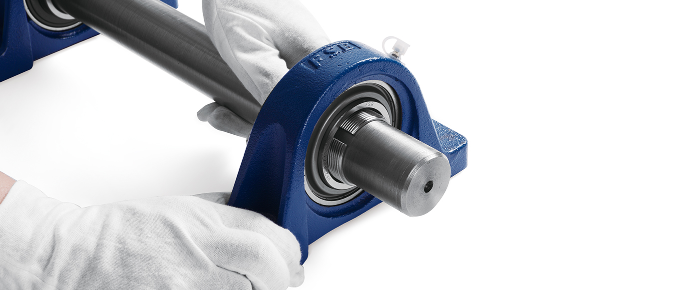
Insert the bearing with seat into the shaft and place it in the specified position.
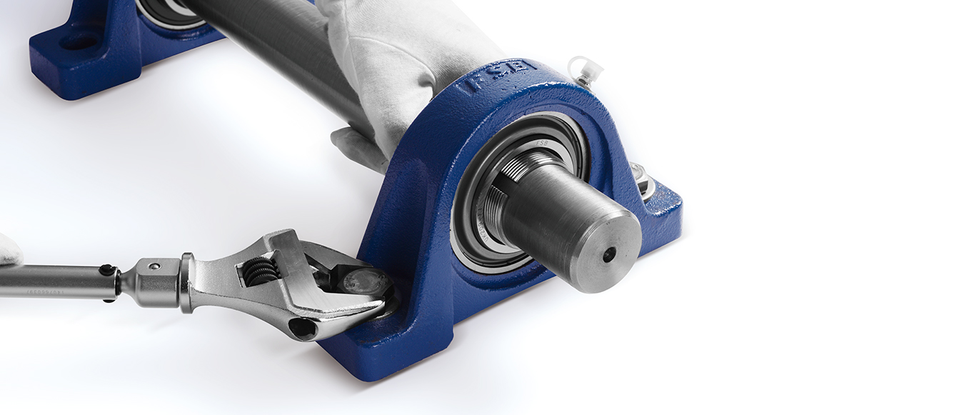
Use a torque wrench to tighten the mounting bolts of the bearing housing according to the specified locking torque.
Recommended table for locking torque of bearing pedestal mounting bolt
| Nominal model of bolt |
Locking torque(±10%) |
|||
| mm |
in |
N.m |
lbf.in |
lbf.ft |
| M6 |
1/4 |
4.0 |
33 |
3 |
| M8 |
5/16 |
8.0 |
71 |
6 |
| M10 |
3/8 |
17 |
151 |
13 |
| M12 |
7/16 |
29 |
257 |
21 |
| M14 |
1/2 |
47 |
416 |
35 |
| M16 |
5/8 |
73 |
646 |
54 |
| M18 |
- |
107 |
947 |
79 |
| M20 |
3/4 |
145 |
1280 |
107 |
| M22 |
7/8 |
200 |
1770 |
148 |
| M27 |
1 |
372 |
3290 |
275 |
| M30 |
1-1/8 |
500 |
4430 |
369 |
| M33 |
1-1/4 |
690 |
6110 |
509 |
| M36 |
1-3/8 |
880 |
7790 |
649 |
Remarks: suitable for P, F, FS, FL, FC, FT, FA, FB, LF, FD bearing pedestal
Install the lock washer and lock nut on the locking sleeve and tighten the lock nut by hand
Use a torque wrench to tighten the locking nut of the locking sleeve according to the specified locking torque
Recommended table of locking torque for lock nut
| Inner diameter model |
Service condition: normal load(Crx0.12>Pr) |
|||||||||||
| UK200Locking torque(±10%) |
UKX00Locking torque(±10%) |
UK300Locking torque(±10%) |
||||||||||
| N·m |
lbf.in |
lbf.ft |
Cr(KN) |
N·m |
lbf.in |
lbf.ft |
Cr(KN) |
N·m |
lbf.in |
lbf.ft |
Cr(KN) |
|
| 05 | 32 | 283 | 24 | 14 | 44 | 389 | 33 | 19.5 | 38 | 336 | 28 | 21.2 |
| 06 | 38 | 336 | 28 | 19.5 | 50 | 443 | 37 | 25.5 | 57 | 505 | 42 | 26.7 |
| 07 | 50 | 443 | 37 | 25.5 | 63 | 558 | 47 | 30.7 | 75 | 664 | 55 | 33.4 |
| 08 | 63 | 558 | 47 | 30.7 | 94 | 832 | 69 | 33.2 | 100 | 885 | 74 | 40.7 |
| 09 | 75 | 664 | 55 | 33.2 | 94 | 932 | 69 | 35.1 | 150 | 1330 | 111 | 48.9 |
| 10 | 94 | 832 | 69 | 35.1 | 138 | 1220 | 102 | 43.6 | 188 | 1660 | 139 | 62 |
| 11 | 125 | 1110 | 92 | 43.6 | 175 | 1550 | 129 | 52.7 | 225 | 1990 | 166 | 71.6 |
| 12 | 163 | 1440 | 120 | 52.7 | 207 | 1830 | 153 | 57.2 | 281 | 2490 | 207 | 81.9 |
| 13 | 188 | 1660 | 139 | 57.2 | 244 | 2160 | 180 | 66.3 | 331 | 2930 | 244 | 92.7 |
| 15 | 213 | 1890 | 157 | 66.3 | 269 | 2380 | 199 | 72.8 | 469 | 4150 | 346 | 113 |
| 16 | 250 | 2210 | 185 | 72.8 | 319 | 2820 | 235 | 83.2 | 563 | 4980 | 415 | 123 |
| 17 | 275 | 2430 | 203 | 83.2 | 369 | 3270 | 272 | 95.6 | 663 | 5870 | 489 | 133 |
| 18 | 325 | 2880 | 240 | 95.6 | 425 | 3760 | 314 | 109 | 763 | 6750 | 563 | 143 |
| 19 | - | - |
- | - | - | - | - | - | 888 | 7860 | 655 | 153 |
| 20 | - | - | - | - | 613 | 5430 | 452 | 133 | 1110 | 9800 | 817 | 173 |
| 22 | - | - | - | - | - | - | - | - | 1530 | 13500 | 1130 | 205 |
| 24 | - | - | - | - | - | - | - | - | 1840 | 16300 | 1360 | 207 |
| 26 | - | - | - | - | - | - | - | - | 2210 | 20500 | 1710 | 229 |
| 28 | - | - | - | - | - | - | - | - | 2690 | 23800 | 1980 | 253 |
| Inner diameter model |
Service condition: normal load(Crx0.12<Pr) |
|||||||||||
| UK200Locking torque(±10%) |
UKX00Locking torque(±10%) |
UK300Locking torque(±10%) |
||||||||||
| N·m |
lbf.in |
lbf.ft |
Cr(KN) |
N·m |
lbf.in |
lbf.ft |
Cr(KN) |
N·m |
lbf.in |
lbf.ft |
Cr(KN) |
|
| 05 | 56 | 496 | 41 | 14 | 79 | 699 | 58 | 19.5 | 68 | 602 | 50 | 21.2 |
| 06 | 68 | 602 | 50 | 19.5 | 90 | 767 | 66 | 25.5 | 101 | 894 | 75 | 26.7 |
| 07 | 90 | 767 | 66 | 25.5 | 113 | 1000 | 83 | 30.7 | 135 | 1200 | 100 | 33.4 |
| 08 | 113 | 1000 | 83 | 30.7 | 169 | 1500 | 125 | 33.2 | 180 | 1590 | 133 | 40.7 |
| 09 | 135 | 1200 | 100 | 33.2 | 169 | 1500 | 125 | 35.1 | 270 | 2390 | 199 | 48.9 |
| 10 | 169 | 1500 | 125 | 35.1 | 248 | 2200 | 183 | 43.6 | 338 | 2990 | 249 | 62 |
| 11 | 225 | 1990 | 166 | 43.6 | 315 | 2790 | 232 | 52.7 | 405 | 3590 | 299 | 71.6 |
| 12 | 293 | 2593 | 216 | 52.7 | 371 | 3280 | 274 | 57.2 | 506 | 4480 | 373 | 81.9 |
| 13 | 338 | 2990 | 249 | 57.2 | 439 | 3890 | 324 | 66.3 | 596 | 5280 | 440 | 92.7 |
| 15 | 383 | 3390 | 283 | 66.3 | 484 | 4280 | 357 | 72.8 | 844 | 7470 | 623 | 113 |
| 16 | 450 | 3980 | 332 | 72.8 | 574 | 5080 | 424 | 83.2 | 1010 | 8970 | 748 | 123 |
| 17 | 495 | 4380 | 365 | 83.2 | 664 | 5880 | 490 | 95.6 | 1190 | 10600 | 880 | 133 |
| 18 | 585 | 5180 | 432 | 95.6 | 765 | 6770 | 565 | 109 | 1370 | 12200 | 1010 | 143 |
| 19 | - | - |
- | - | - | - | - | - | 1600 | 14100 | 1180 | 153 |
| 20 | - | - | - | - | 1103 | 9760 | 814 | 133 | 1990 | 17600 | 1470 | 173 |
| 22 | - | - | - | - | - | - | - | - | 1750 | 24300 | 2030 | 205 |
| 24 | - | - | - | - | - | - | - | - | 3310 | 29300 | 2440 | 207 |
| 26 | - | - | - | - | - | - | - | - | 3980 | 35300 | 2940 | 229 |
| 28 | - | - | - | - | - | - | - | - | 4840 | 42800 | 3570 | 253 |
| Cr=Basic dynamic load rating,Pr=equivalent dynamic load |
||||||||||||
Bend the claw (1 piece) of the washer which is consistent with the notch position of the outer diameter surface of the lock nut to the notch position of the outer diameter surface of the lock nut to prevent the lock nut from loosening.
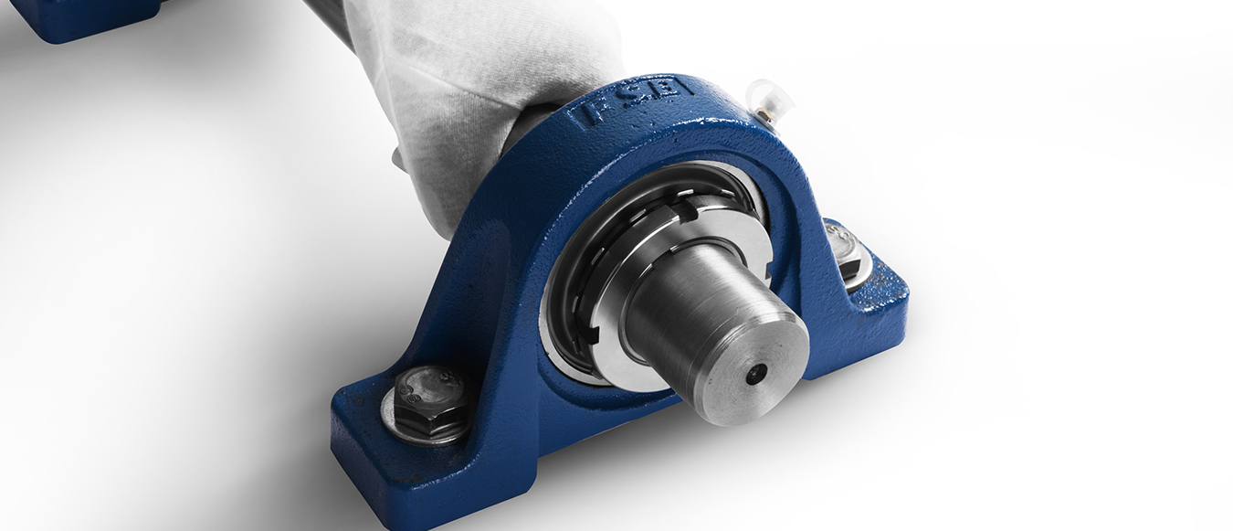
Rotate the shaft by hand to confirm whether the rotation state of the bearing is abnormal.